
Tel.: +86-150 7112 0854 Email: abby@tensense-geotech.com


Ultrasonic hole drilling and detection technology, due to its wide range of adaptability, intuitive measurement data, and high accuracy, has been widely adopted in large-scale construction projects. In addition to this, there are special-purpose ultrasonic detection equipment developed by some units. This analysis focuses on the technical issues encountered in the application of ultrasonic principle-based detection equipment, serving as a reminder for users to be aware of these considerations.
In borehole drilling and detection, both processes are carried out with mud inside. Relative to water, mud exhibits a much higher absorption of sound waves, and this absorption is subject to variability. Freshly prepared mud typically absorbs fewer ultrasonic waves, where as recycled mud often shows an absorption rate approximately 40dB/m higher than that of fresh mud.
When encountering strata with quicksand layers at the drilling site, the recycled mud contains a greater amount of suspended sand and silt particles. These particles cause a substantial attenuation of ultrasonic energy as it travels, and in extreme cases the energy may be completely dissipated before it even reaches the borehole wall, leading to a failed test.
In light of this, from the user’s perspective, it is necessary to appropriately increase the ratio of fresh mud and implement measures to reduce the content of suspended sand and silt in the mud. From the designer’s perspective, there is a need to improve the equipment’s adaptability to different mud concentrations.
Currently, the measurement accuracy of ultrasonic hole drilling and completion detection equipment is generally around 0.2%. Measurement accuracy is influenced by a multitude of factors, such as the varying degrees of ultrasonic wave absorption by circulating mud; the non-uniformity of sound velocity distribution in the mud within the borehole; and the characteristics of the ultrasonic sensors, among others. Since the mud is continuously circulating during the drilling process, and the construction of diaphragm walls stirs the mud due to the lifting and lowering of the grab, it is difficult to ensure that the mud temperature is consistent across different locations and times of drilling. It is necessary to calibrate the impact of mud temperature on measurement accuracy before taking measurements, which should be given due attention in practical operations.
As is well known, the performance of a signal in the frequency domain and the time domain are often contradictory. That is to say, to ensure precise measurement in the time domain, there must be a guarantee in the frequency domain. To achieve a time-domain measurement accuracy of 0.2%, the ultrasonic system must meet certain bandwidth requirements; otherwise, the time-domain measurement accuracy cannot be guaranteed.
Currently, the technique of drilling and grouting piles is also being adopted in the construction of urban residential buildings, with considerable depths involved. The characteristic of these drilled and grouted piles is that they have a smaller diameter, and the design itself requires a lower degree of perpendicularity compared to those in large municipal projects. The capabilities of drilling rigs during the construction process are relatively limited, and the perpendicularity deviation after hole completion is also significant. From a quality control perspective, these types of drilled and grouted piles are in greater need of monitoring. However, the current ultrasonic borehole & diaphragm wall testing technology is not suitable for such drilling holes. Although there have been practical applications, the observed data is not convincing enough to be relied upon and can only serve as a general reference. The following analysis will delve into the reasons behind this issue.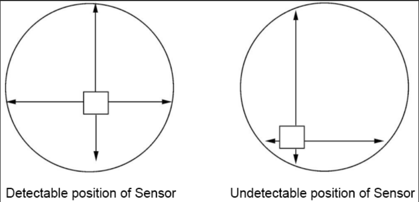
The square in the above figure represents the ultrasonic sensor, the equipment in this article belongs to this form of measurement. Blind zone is mainly due to the ultrasonic emission frequency is generally not high enough, the system’s bandwidth is limited, in the time domain for the launch of ultrasonic pulses have a certain duration, if the use of transceiver combined operating mode, echo wave can not be received before the pulse emitted.
Left figure is a normal measurement, at this time, there is a certain distance between the transducer and the wall of the well, the distance is greater than the blind zone, the measurement data is credible. Right figure in the left direction and the lower direction because the ultrasonic transducer leaves the borehole wall too close, has entered the blind zone, so the measurement data is not credible. In actual use, serious cases can be found only one direction of the measurement data is credible. Users often think that the equipment is out of order, but in fact, it is not, it is the blind spot caused by the inability to measure. So the current ultrasonic drilling hole detection equipment is not suitable for small hole diameter drilling measurement.
For for some borehole that doesn’t have a strict perpendicularity requirement may also occur such a problem. In order to reduce the impact of the blind spot, from the point of view of ultrasonic technology is mainly to increase the bandwidth of the system, for this reason, the domestic expansion of the bandwidth of the bandwidth, to more than twice the imported equipment, so the blind spot is smaller than the foreign 50mm or so. Measures to reduce the blind spot and the use of transceiver discretionary mode, the use of the transceiver is a split mode, but because of its transducer geometry is relatively large, so the blind spot is small did not really reflect the test on the
It is not uncommon to see borehole diameters measured directly from ultrasonic observations on the construction site. If the borehole is not deflected and the ultrasonic transducer has been accurately placed in the centre of the borehole before it is lowered, the direct measurement of the borehole diameter will be correct. In practice, however, it is difficult to guarantee that the hole diameter cannot be measured directly from the observation chart. A simple calculation is given below to derive the hole diameter. The solid circle in figure below is the horizontal contour line of the borehole at a certain depth, O is the centre of the borehole; since the centre of the borehole is offset, the centre of the transducer is not offset and remains at the central position O′. The absolute value of the offset of the borehole is the distance between O-O′. The ultrasonic hole-forming quality tester gives four quantities of distance X, X′, Y, Y′ away from the sensor centre O′ in four orthogonal directions
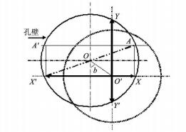
As indicated by the four arrows in the figure, in order to calculate the distance O-O′, the parallel A-A′ of X-X′ is added to figure above, and the intersections of A-A′ with the circle of the borehole wall, A and A′, are connected with X and X′, X, X′, A, A′ then form a rectangle, the diagonal of which passes through the centre of the circle of the borehole wall, the length of which is the diameter of the borehole at this depth.
It is easy to see from the graph that the expression for the diameter is:
![]()
And same :
![]()
Eccentricity at the depth:
![]()
For diaphragm walls, the eccentricity is described by the degree of deviation in a single direction at that depth
![]() Test on direction of X
Test on direction of X
or
![]() Test on direction of Y
Test on direction of Y
In engineering applications to calculate the perpendicularity of the diaphragm wall into the groove K is often used at the top of the groove (guide wall) measured in a certain direction (such as the Y direction) of the value of Yo minus the bottom of the groove measured in this direction of the YL value and then divided by the depth of the groove L, the formula is
![]()
Offset azimuth of drilled holes
![]()
There are two preconditions for the correctness of the process of calculating the hole diameter: (i) the wall of the hole is circular in the horizontal plane; and (ii) the centre O′ of the sensor remains constant.
The first condition can be satisfied if there is no collapsed hole, that is, it is difficult to determine the centre of the circle as the horizontal plane of the borehole is not necessarily a circle when there is a collapsed hole.
The second condition requires that the centre of the sensor be kept constant at all times, which is a requirement for the measuring instrument. The main reasons for the variation of the sensor centre are:
(i) The torque generated by the rotation of the cable suspending the sensor. Any cable will rotate, thus causing the sensor centre instability, which is more prominent in mechanical
This is more prominent in the mechanical type.
② Measuring equipment using sensor rotation. Due to the sensor’s own rotation caused by the sensor centre of the offset, resulting in the measurement of the perpendicularity of the azimuth data to produce a significant deviation, which is also a weakness of this type of equipment.
③ Structure of the sensor. As the sensor is suspended in the hole, the weak force after tens of meters of depth may cause the sensor centre to shift, the reasonable design of the sensor shape structure is essential to improve the stability of the measurement data of this type of equipment.
④ Stability of mud in the drilling trough. This factor should be paid particular attention to in diaphragm wall measurement. Generally, we should wait for the mud in the trench to be stable after the completion of the trench construction before testing, especially to avoid a trench being tested while the adjacent trench is under construction, which will disturb the mud in the trench and cause the sensor centre to shift, resulting in the distortion of the measurement data.
The so-called perpendicularity of the hole (slot) refers to the extent to which the centre of the drill hole deviates from the centre of the drill hole required by the design. The centre of the hole required by the design should usually be the centre point of the hole opening at the start of drilling. As the drill bit advances downwards, the centers of the holes at different depths are difficult to coincide with the centre of the hole opening in the direction of gravity, and a certain amount of deviation will occur, and in order to describe the degree of this deviation, the concept of the perpendicularity of the drilled hole (slot section), K, has been introduced. It is defined as
![]()
Where: K for the hole (slot section) perpendicularity; E for the hole (slot) eccentricity (unit: m); L for the hole (slot) measured depth (unit: m).
Theoretically, the value of E in equation (8) should be the measured eccentricity of the bottom of the hole (slot) (at the maximum depth L). If the deflection of the hole (slot) is unidirectional, that is to say, from the top to the bottom of the borehole is always biased in a fixed direction, the calculation results of formula (8) can accurately express the degree of deflection of the hole.
The result of equation (8) can accurately express the degree of deflection of the borehole. However, if a hole is not always deflected in a fixed direction, e.g., if the hole is deflected in direction X at the top of the hole and then deflected in the opposite direction X′ at a certain depth, the centre of the hole at the bottom of the hole will almost coincide with the centre of the hole required by the design.
The perpendicularity of such a borehole calculated according to the above formula is almost 0, which means that the perpendicularity of this borehole is very good. However, this is not the case in reality, if the drill hole has reached a relatively large deviation value at a certain depth, even if the perpendicularity data of this hole is good, it is possible that the cage cannot be lowered smoothly. This should be noticed by the constructor.
The calculation of the perpendicularity of the slot section is relatively simple, usually just use the deviation value in the Y-Y′ direction to replace the E value in the perpendicularity formula. Similarly, using perpendicularity to measure the perpendicularity of the channel section has the same problem as in the case of borehole measurements.