
Tel.: +86-150 7112 0854 Email: abby@tensense-geotech.com

Tel.: +86-150 7112 0854 Email: abby@tensense-geotech.com

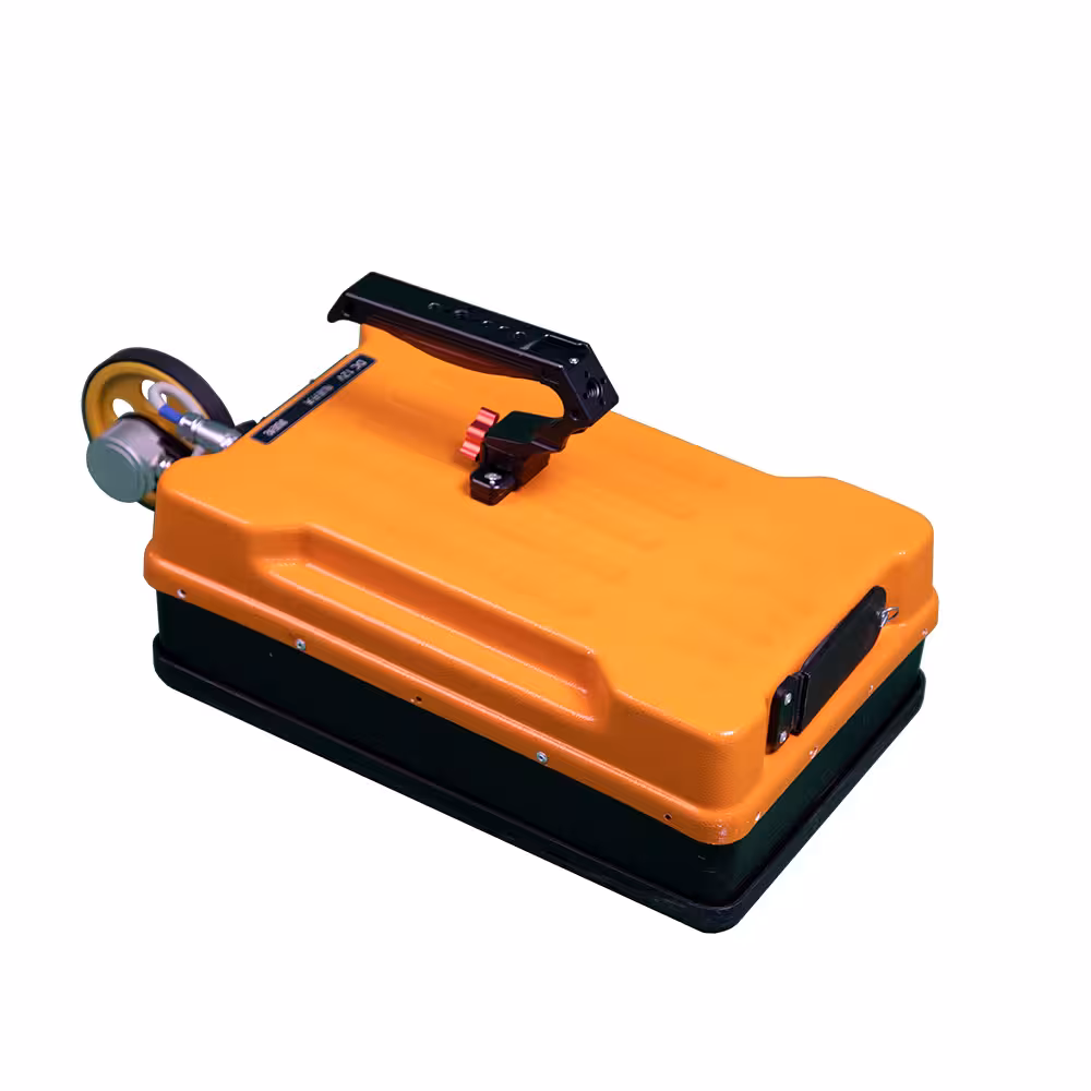
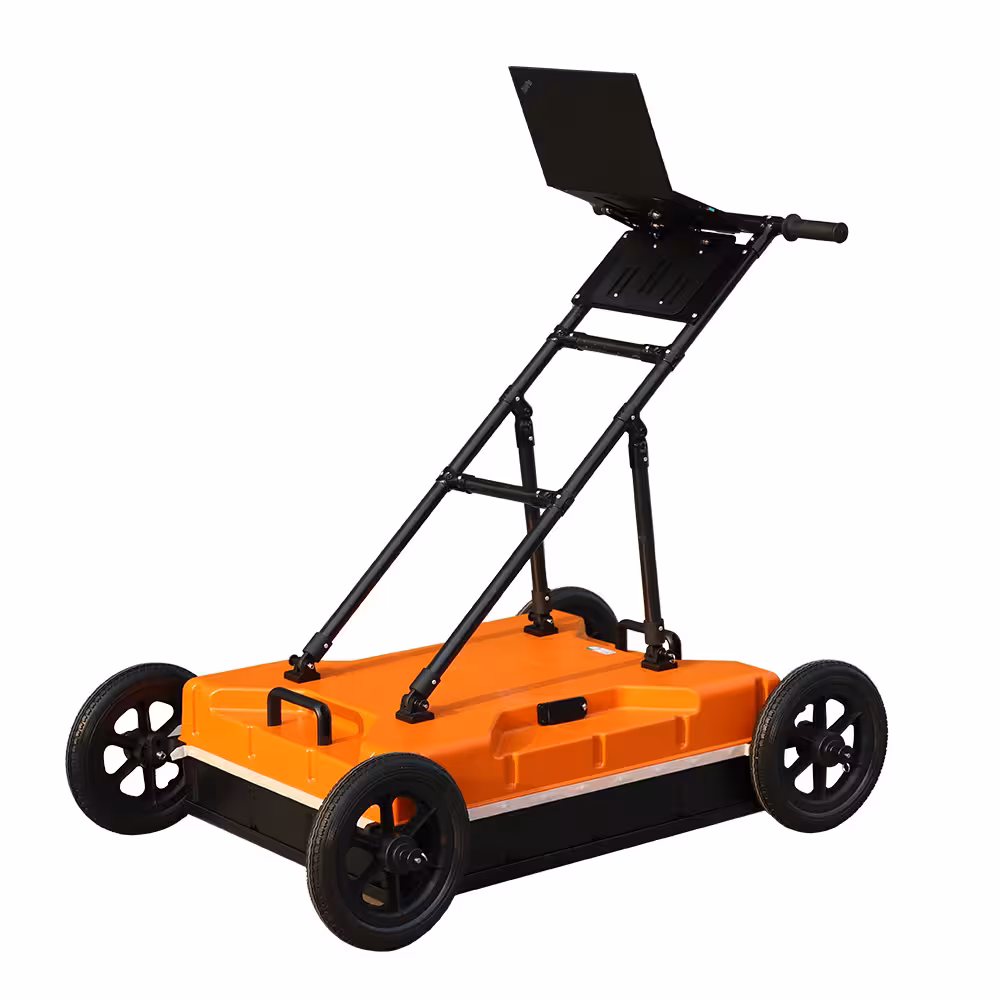
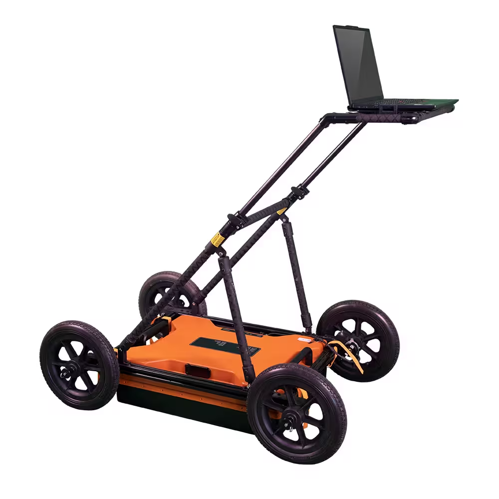
Tensense TS-WGR1201(B)-600 is a high-precision wireless Ground Penetrating Radar engineered for professional subsurface inspection and engineering analysis. Operating at 600 MHz, it delivers superior resolution for depths of 1–3 m, making it ideal for engineering structure inspection, tunnel lining evaluation, retaining-wall defect detection, and detailed geotechnical surveys.
High-resolution subsurface imaging for concrete, soil, rock, and composite materials.
Wireless communication with up to 50 m range and Ethernet support for secure data transfer.
Multi-antenna compatibility for combining high-resolution shallow data with deeper low-frequency scans.
Extended battery life (8+ hours) for uninterrupted fieldwork.
Advanced software suite with 2D/3D visualization, layer tracking, void detection, and CAD/GIS export.
Ground Penetrating Radar (GPR) is widely applied in geological hazard assessment, geotechnical engineering investigations and design, as well as in various civil infrastructure inspection projects. It is capable of detecting and identifying both metallic and non-metallic subsurface targets within a certain depth. The main applications include:
Geological Hazard Assessment:
GPR is used to detect subsurface anomalies such as voids, cavities, and fractured zones that may pose potential geological risks.
Geotechnical Engineering Investigation:
In engineering site investigations, GPR helps identify underground anomalies such as karst features, collapse zones, and fractured belts, providing critical data for design and risk control.
Municipal Utility Mapping:
GPR is utilized in urban construction to locate and map underground metallic and non-metallic pipelines, reducing the risk of accidental damage during excavation.
Road and Bridge Surveys:
It supports the detection of unfavorable geological conditions during the site selection and construction of roads and bridges, contributing to safer and more reliable designs.
Tunnel Inspection and Forecasting:
GPR is used for advanced geological prediction in tunneling and for inspecting the quality and integrity of tunnel structures during and after construction.
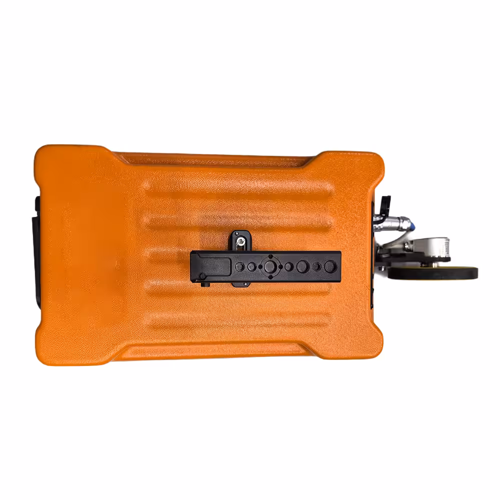
Compact and Integrated Design
The system features an industry-leading integration of control unit and antenna, resulting in a compact, lightweight, and low-power design—ideal for field deployment and mobile operations.
Wireless and Real-Time Operation
With wireless communication between the main unit and the computer, users benefit from greater flexibility and ease of operation. The system supports real-time data acquisition and display, enabling immediate interpretation and decision-making on site.
User-Friendly Software Interface
The software offers a clean, intuitive interface that is easy to operate and quick to learn, reducing training time and improving operational efficiency.
Flexible Frequency Options and Broad Application Range
A variety of antenna frequency configurations are available to suit different application needs—from shallow, high-resolution scans to deeper, low-frequency surveys—making the system adaptable across diverse geophysical and infrastructure scenarios.
Accurate Data Analysis and Interpretation
Equipped with easy-to-use analysis software, the system ensures accurate data interpretation and dependable subsurface imaging results.
High Detection Precision and Target Localization
Advanced signal processing enables high-resolution detection and accurate positioning of subsurface targets, ensuring reliable performance in complex environments.
Extended Battery Life
An internal high-capacity battery supports long-duration operation, reducing downtime and enhancing productivity in the field.
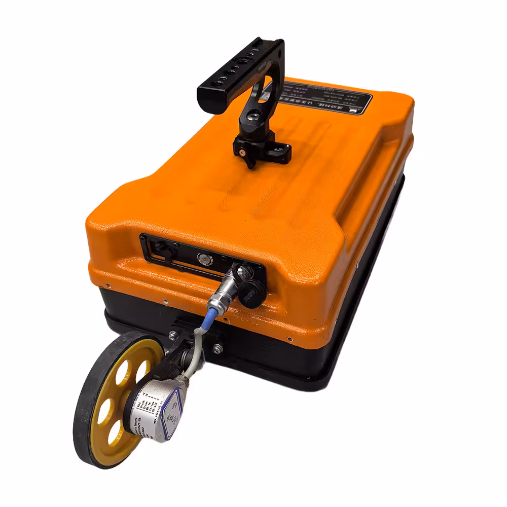
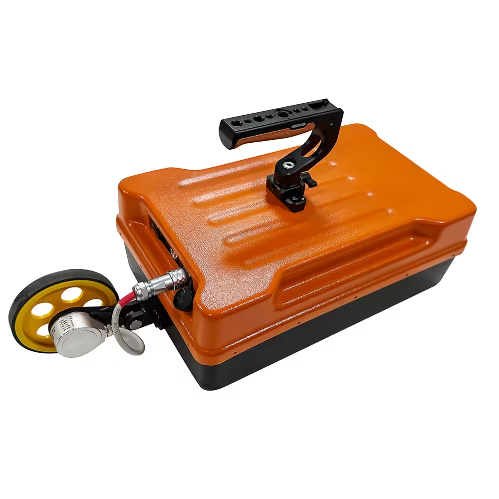
Ergonomic and Durable Construction
Designed with ergonomics in mind, the system is simple to operate, rugged in construction, and highly durable—perfectly suited for demanding outdoor environments and mobile survey conditions.
| Hardware | Items | Specification |
| Antenna Frequency | 600 MHz | |
| Sampling Frequency | Adjustable from 0.2–100 GHz | |
| Time Window | 1 ns – 20000 ns, continuous adjustable | |
| Points per Scan | 32 – 32767 points/scan, Ajustable | |
| Scanning Speed | 512 scans/sec | |
| A/D Conversion Accuracy | 18-bit | |
| Maximum Transmission Frequency | 600 kHz | |
| Continuous Working Time | ≥8 hours | |
| Power Consumption | ≤16 W | |
| Signal-to-Noise Ratio | > 160 dB | |
| Acquisition Speed | >60 km/h at 5 cm horizontal sampling interval (road mode) | |
| Minimum Sampling Interval | <10 ps | |
| Working Modes | Point-based, distance-based, continuous, GPS-based | |
| Display Modes | Color-scaled map,Waveform stack,Grayscale map | |
| Operating Temperature | -30°C to +70°C | |
| Operating Voltage | 10–15V DC | |
| Ingress Protection | IP66 | |
| Wireless Distance | Up to 50 m | |
| Wired Communication | Ethernet, 100 Mbps | |
| Weight | <5 kg |
Software | System | Sampling Parameter | Number of Samples |
|
Sampling Rate |
| |||
Pulse Repetition Frequency (PRF) |
| |||
Traces per Acquisition |
| |||
Averaging Factor |
| |||
Start Position |
| |||
Scan Start |
| |||
Time-Zero Position |
| |||
Center Frequency |
| |||
Distance Measure Tool Parameters | Measurement Diameter |
| ||
Distance Correction |
| |||
Wheel Spacing |
| |||
Measuring Parameter | Stacking/ Stack Count |
| ||
Refresh Traces |
| |||
Survey Mode | Continuous Time, Wheel, Point | |||
Display Scale |
| |||
Step Size |
| |||
Filter | Filter Setting | Dewow Filter | True / False | |
Band-Pass Filter | True / False | |||
Low-Cut Frequency |
| |||
High-Cut Frequency |
| |||
Display | Display Setting | Multi-Channel Layout | Horizontal / Vertical | |
Time-Zero Offset |
| |||
Show Markers | True / False | |||
Show Title | True / False | |||
Show Horizontal Grid | True / False | |||
Show Vertical Grid | True / False | |||
Trace Start Index |
| |||
Trace End Index |
| |||
Display Points |
| |||
Display Start |
| |||
Color Scheme (4 choices) |
| |||
Relative Dielectric Constant |
| |||
Vertical Pixels |
| |||
Horizontal Pixels |
| |||
Gain | Gain | SEC Gain | True / False | |
SEC Initial Value | Adjustable | |||
SEC Attenuation | Adjustable | |||
SEC Max Value | Adjustable | |||
Constant Gain | Constant SEC Gain | True / False | ||
Display Gain | True / False | |||
| Coordinate Setting | Horizontal Axis | Trace Number / Distance | |
Vertical Axis | Time / Depth / Sample Point | |||
Toolbar | File | Open File |
| |
Save File |
| |||
Acquisition | Device IP |
| ||
Connect |
| |||
Disconnect |
| |||
Start Acquisition |
| |||
Stop Acquisition |
| |||
View | Image + Wiggle |
| ||
Image Only |
| |||
Wiggle-Trace Stack |
| |||
Wiggle Plot |
| |||
3-D View |
| |||
Increase Amplitude |
| |||
Decrease Amplitude |
| |||
Stretch Horizontally |
| |||
Compress Horizontally |
| |||
Stretch Vertically |
| |||
Compress Vertically |
| |||
Full Screen |
| |||
Processing | Delete Trace |
| ||
Auto Gain |
| |||
Segmented Gain |
| |||
Exponential Gain |
| |||
IIR Low-Pass |
| |||
IIR Band-Pass |
| |||
FIR Band-Pass |
| |||
FIR Low-Pass |
| |||
Report | Generate Report |
No. | Item | Qty | Unit | Description |
1 | Integrated GPR Antenna | 1 | pc | 600 MHz Shield Antenna |
2 | Real-time Acquisition & Analysis Software | 1 | set | No hardware lock |
3 | Dedicated Rechargeable Battery | 1 | set | Supports continuous operation for over 8 hours |
4 | Dedicated Charger | 1 | set | Supports both fast and slow charging |
5 | User Manual | 1 | pc | — |
6 | Professional Data Processing Software | 1 | set | — |
7 | Laptop / Tablet | 1 | pc | Optional |
8 | Distance Measure Tool | 1 | set | Optional |
9 | Professional Trolley | 1 | unit | Optional |
Uploading…