
Tel.: +86-150 7112 0854 Email: abby@tensense-geotech.com


Case-in-place concrete piles are often chosen as a deep foundation alternative where challenging soil conditions exist and/or where vibrations from the pile driving are unacceptable. Although quality control measures are almost always taken during the initial installation of the foundations, it is often difficult or impossible to confirm the integrity of a drilled shaft during construction, particularly in wet conditions. We noticed a testing sample as below , out of 441 drilled shafts tested on multiple projects, approximately 75% of the projects had at least 1 shaft containing an anomaly and 33% of all shafts tested contained at least 1 anomaly.Drilled shafts often have significantly higher design loads than driven piles and therefore are less repetitive, quality assurance of each drilled shaft is essential for each project.
Non-destructive test (NDT) methods after installation have become the standard in quality assurance of drilled shaft foundations. Several methods are available to perform this testing. Among the most common methods of NDT testing are cross-hole sonic logging and low-strain integrity testing. Individually, each test method has it’s own advantages and weakness inherent in the test method. These advantages and weakness are discussed in this article. When both test methods are used in conjunction, certain characteristics of potential defect may be clarified. This article presents a case history where anomalies are indicated by both test methods. The results of the two test methods are compared. Core drilling also confirmed the anomalies as defects.
Cross-hole sonic logging(CSL) is a NDT method which involves ultrasonic signal transmission through the shaft between 2 ore more parallel water filled access tubes. The access tubes are foten tied to the rebar cage and cast permanently into the shaft. The total number of access tubes typically depends on the diameter of the shaft.A transmitter probe and a receiver probe(or more) are lowered to the bottom of the shaft in separate access tubes. Measurements of the signal transmission are collected approximately every 5cm as the probes are raised to the top of the shaft. The cables attached to the probes are pulled through calibrated encoder wheels which can accurately determine the depth of the probe during test. A collection of measurements from one access tube to another are called a profile. Profiles are collected from all combinations of access tubes.
The interpretation of CSL results requires experience and understanding of the capabilities and limitations of the method.Shaft quality assessment from CSL is primarily based on the first arrival time (FAT) of the signal. The concrete wave speed can be estimated by dividing the distance between the access tubes by the FAT. The wave speed of concrete can be used as a judgment of the over all concrete quality because wave speed is related to the concrete compressive strength. However , during placement of the rebar cage or concrete, the access tubes often move slightly out of parallel and ultimately the distance between the tubes is not always constant with depth.Therefore, it is more practical to evaluate the FAT as a relative measurement for each individual shaft, comparing signal delays to a “running” average of data from the same shaft. Often a running average of approximately 75 consecutive data points, which would represent approximately the surrounding 3.75m, are averaged for comparison to evaluate a local defect.
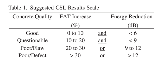
Signal strength is another important measurement for evaluation of CSL data. The signal strength is converted to signal “energy” by integrating the signal over a defined time Relatively low energy can indicate poor quality concrete or a defect in the shaft. Often a major defect will causes both a significant FAT delay and decrease in relative energy Interpretation of a major defect from CSL is often intuitive, however, evaluating a relatively minor FAT delay or energy decrease requires engineering judgment. Table 1 below is a suggestion scale and description after.
Flaws should be addressed if they are indicated in more than 50% of the profiles. Defects must be addressed if they are indicated in more than 1 profile. Addressing a flaw or defect should include, at a minimum , an evaluation by tomography if the area of concern is localized, and/or additional measures such as excavation, core drilling, or pressure grouting. Defects or flaws indicated over the whole cross-section usually require repair or replacement
2.2 CSL Advantages
2.3 CSL Disadvantages
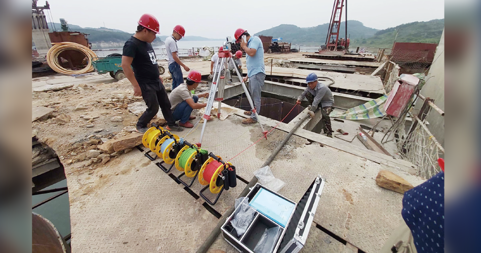
Low-strain integrity testing, also know as Pulse Echo Method(PEM)or Pile Integrity Testing(PIT), is a NDT based on wave propagation theory. The pile top is impacted with a handheld hammer and the resulting pile top motion is measure via an accelerometer attached to the pile top. The hammer impact creates a low strain compression stress wave that propagates down the pile. The wave is reflected when a changing in “impedance”, the pile toe or soil resistance effects are encountered. Impedance is related to a pile’s cross section area, elastic modulus, and stress wave propagation speed. An impedance reduction causes a reflected compressive wave(a decrease in the velocity curve). High soil resistance can also cause compressive reflections which can sometimes be minimized through filtering techniques. Figure 2 shows a typical field test using the pile integrity tester. Low strain integrity testing has many potential applications. The most typical application is to evaluate newly constructed shaft as a quality control measure. Recently, the evaluation of existing foundation has become more relevant in urban construction or historical structures.Low-strain integrity testing can be an effective tool in evaluation shaft lengths and quality.
In order to fully evaluate shaft integrity using low strain integrity testing results, a clear toe reflection in the velocity record must be observed. When the length of the shaft is known, the appropriate material wave speed can be applied to the record. Tensile reflections that occur prior to the toe reflection can be investigated to determine if any impedance reductions occur in the shaft.Several factors can deplete the strain wave and therefore diminish any observable toe reflection.These factors include high soil resistance, several minor or one major impedance change, and excessive length.Piles with length to diameter impedance change, and excessive length. Piles with length to diameter ratios above 30 often have excessive damping due to soil resistance and/or pile material properties which deplete the strain wave and cause no observable toe reflection, although this rule can sometimes be deviated and piles with a greater ratio can be reasonable tested under special circumstances.
Both of these NDT methods are effective tools in quality assurance and foundation evaluation. The advantages and disadvantages of each individual test method have been discussed. The two test methods also inherently have similarities and differences in their application and result.
CSL can only evaluate the concrete between access tubes while PIT can evaluate the full cross section as well as profile of the shaft
CSL can estimate depth , horizontal position, and extent of a defect, PIT only indicates the depth and only a very rough estimate of the extent
CSL is effective in identifying a “soft toe” condition while PIT can not be reliable for this application (due to variations in concrete wave speed)
Both of these 2 test methods can be used on the same shaft. In conjunction, the combined test results provide a more comprehensive evaluation of the shaft than either single test alone. For example, if PIT testing indicates and impedance decrease at a certain depth however CSL result do not indicate FAT delays or energy decreases at the corresponding depth, it is likely that the impedance decrease indicated from PIT results is from a reduction in cross section and not from a material quality issue.