Tel.: +86-150 7112 0854 Email: abby@tensense-geotech.com
Tel.: +86-150 7112 0854 Email: abby@tensense-geotech.com

Ultrasonic testing is a critical method for evaluating the diameters and verticality of boreholes and diaphragm walls. The Tensense Ultrasonic Borehole Monitor utilizes high-frequency sound waves to measure the diameters, verticality, sediment thickness of borehole and diaphragm wall, as well as to shape the borehole walls. However, the accuracy of the test results heavily relies on the proper configuration of two key parameters: Gain (G) and Beta (b). These parameters directly influence the clarity of ultrasonic waveforms, enabling the distinction between valid signals (e.g., primary echoes) and noise (e.g., secondary reflections). This article provides a technical guide to adjusting G and b parameters, emphasizing their roles, correct calibration methods, and consequences of improper settings.


Definition:
Gamma Gain (G) is a nonlinear amplification parameter that enhances weak signals disproportionately to strong ones. It applies an exponential adjustment to the received waveform, prioritizing the visibility of low-amplitude echoes (e.g., deep defects) without saturating high-amplitude signals (e.g., near-surface reflections).
Function:
Technical Basis:
The output signal Sout is derived from the input signal Sin using:
Sout=Sinγ(γ=G value)
A higher G value (γ>1) increases contrast for weak signals but risks amplifying noise.
Definition:
Beta Gain (b) is a dynamic compensation parameter that adjusts amplification linearly with depth or time. It compensates for ultrasonic energy loss due to material attenuation (e.g., scattering in concrete).
Function:
Technical Basis:
The gain curve is often defined as:
Gain(t)=b0+b1*t(t=wave travel time)
Here, b1 controls the slope of gain increase over time.
In practical operations with the Tensense Ultrasonic Borehole Monitor, Beta Gain (b) parameters typically require minimal adjustment unless significant attenuation is observed.
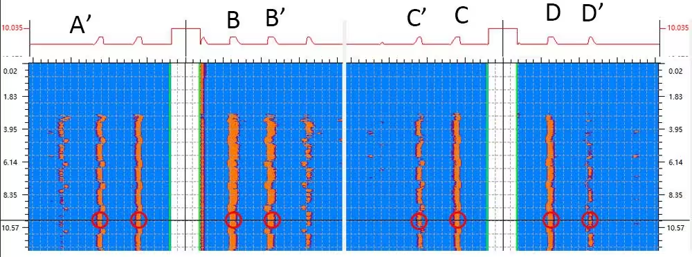
Before testing, ensure the probe is properly coupled to the borehole. Acquire a baseline waveform (Figure 1). A qualified waveform should display:
Primary Echoes (A, B, C, D): Clear, high-amplitude peaks corresponding to valid reflections at interfaces (e.g., pile boundaries).
Secondary Echoes (A’, B’, C’, D’): Lower-amplitude noise caused by multiple reflections or structural reverberations.


Figure 1: Qualified waveform with distinct primary (A-D) and secondary (A’-D’) echoes
And at some situations, there also maybe third echoes, fourth echoes….
Enhance Weak Signals:
Apply moderate G values (1–9) to amplify deep or faint echoes without distorting primary peaks.
Noise Suppression:
If secondary echoes (A’–D’) become prominent, reduce G to prevent noise amplification.
Example Workflow:
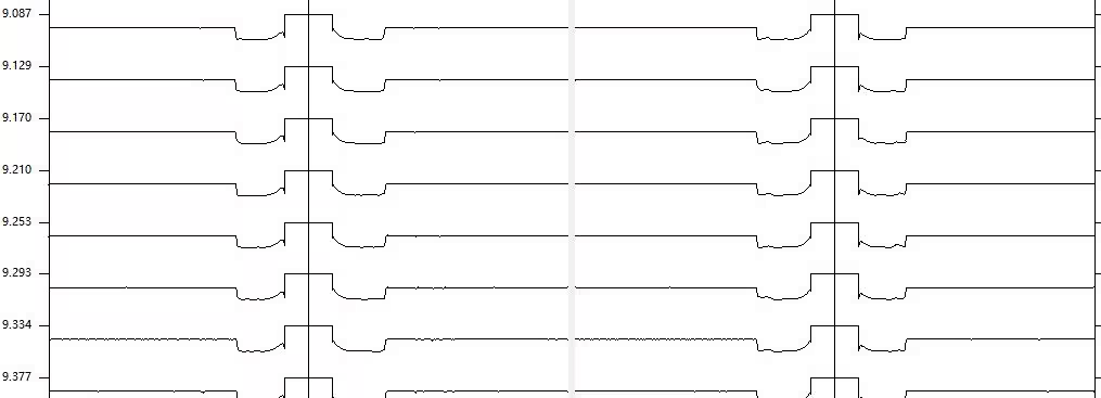
Result: A well-configured waveform (Figure 2) shows sharp primary echoes and suppressed noise.


Symptoms:


Figure 3: Failed waveform with indistinguishable echoes
Symptoms:


Figure 4: Uninterpretable image due to low gain
Calibration with Reference Data:
Use test piles with known defects to optimize G and b.
Iterative Adjustment:
Adjust b first to balance depth-wise signals, then refine G for contrast.
Noise Monitoring:
If secondary echoes dominate, reduce G or apply signal filtering.
Proper configuration of G and b parameters is pivotal for accurate ultrasonic testing. Gamma Gain (G) enhances critical details in weak signals, while Beta Gain (b) ensures uniform signal strength across depths. Misconfigured gains lead to ambiguous waveforms and unreliable reports. By following the guidelines above, engineers can achieve clear, interpretable results, ensuring the structural integrity of boreholes and diaphragm walls.